The main principle of transistorized ignition systems is to use transistors as electronic switches instead of breaker points.
For those of you who already know about vehicle ignition systems, you should know the breaker point or platinum.
Breaker point is a device used to break the primary coil current in the ignition coil so that electromagnetic induction can occur. This breaker point works mechanically by utilizing a cam that can stretch the breaker point gap.
However, the use of breaker points is considered to be less effective, it is because the rubbing components will erode so that it can affect the overall ignition system performance. In addition, when the breaker point is stretched, frequent sparking occurs at the breaker point so that the induction power of the ignition coil is reduced.
That's why there is breaker point gap adjustment.
By utilizing transistors the two things above can be overcome. So we don't need to set the gap.
Why are transistors used instead of breaker points?
As we said at the beginning, the transistor has a function as an electronic switch. There are three legs on the transistor namely base, collector, and emitter.
Collector is input, while emitter is output. The base as a controller, if there is an electric current (low voltage) flows at the base then the current at the input (collector) will flow to the output (emitter).
However, when the electric current at the base stops, the collector is cut off again with an emitter.
So in conclusion, the transistor can be used in the ignition system because of its characteristics that can disconnect and connect lines quickly.
To control the performance of the transistor, we need one additional sensor, the pick up coil. This sensor will send a low-voltage current with pauses according to the ignition timming at the base foot. So that the transistor performance will be matched with the engine RPM.
How does the coil pick up work?
Pick up coil consists of three parts, namely rotor with cam, permanent magnet and coil.

The three components are placed as shown, it is confirmed that the permanent magnet emits a magnetic field that hits the rotor. While the rotor is made of metal which is able to be attracted by magnets.
Cam on the rotor serves to shorten the gap between the rotor with a permanent magnet.
This changing gap causes the current in the pickup coil to be zig-zag. When the cam is parallel to the permanent magnet there is an electric current, but when the cam shifts the current disappears. This drop voltage is used as timming to break the primary current in the ignition coil.
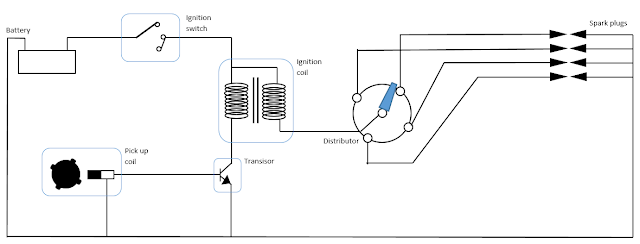
Transistorized Ignition System diagram

- Battery
- Ignition switch
- Ignition coil input
- Primary coil output
- Secondary coil output
- Transistor
- Pick up coil
- distributor
- Spark plug
Transisorized ignition system working procedure
When the engine is started, the crankshaft will rotate the pick up coil so that the pick up coil generates a low voltage current. This will cause the transistor base to be active so that the collector is connected to the emitter.
In the ignition coil, the current from the battery will flow in both coil in the ignition coil.
As explained above, the pickup coil will generate zig-zag electric current. Current from the pick up coil is then transmitted to the base leg of the transistor.
Induction in the ignition coil occurs when the base foot does not get an electric current, but it lasts for an instant, therefore in one cycle of the 4 cylinder engine can occur four times the induction process.
The induction produces high voltage which is distributed to the distributor to be distributed to each spark plug according to the firing order. Sumber https://www.autoexpose.org/